Nr kat. prod. 240-131
BREADBOARD TERM STRIP 3.29X2.15"
Digilent, Inc.
License: See Original Project
Sometimes, things go wrong when working with simple logic gate ICs. Problems can include seemingly incorrect results or ICs that don’t seem to react at all. However, it’s often difficult to determine whether a broken chip causes an issue or whether there’s a problem with the circuit. Often, it’s best to remove the potentially damaged chip from the build and test it independently from the other components in the electronics design. This article discusses a simple Arduino-based logic IC tester you can employ to find problems in your digital circuits.
This image shows the completed build.
BOM
Part/Quantity
Solderless breadboard - 1
5mm LED; red - 1
5mm LED; green - 1
Resistor; 150 Ohm - 2
Pushbutton - 2
Arduino UNO - 1
Quad NOR Gate - 1
Quad AND Gate - 1
The Basics of the 7400-Series of Logic Gate ICs
This logic gate IC tester design functions because most standard four-gate 7400 logic ICs utilize the same physical pin layout, as the following image illustrates:
This image contains three package diagrams of common logic ICs. The first two implement positive functions (OR and AND), and the third IC implements a negative logic function (NOR). Note how the I/O pins are swapped between some positive and negative packages. Image source: https://www.ti.com/lit/gpn/sn74ls32, https://www.ti.com/lit/gpn/sn74ls08, https://www.ti.com/lit/gpn/sn5428
Note that the GND pin is always located in the bottom-left corner of 7400 series chips, and VCC is always tied to pin 14. The pins labeled with A and B are inputs, and the pins labeled with Y are outputs. Most 7400 logic ICs are pin compatible. However, it’s good to know that the inputs and outputs are swapped on some inverted logic ICs, such as the NOR gate on the far right of the image. You should keep that in mind, as supplying an output pin with a signal will most likely cause irreparable damage to the IC. The IC tester discussed in this article can test both kinds of ICs. Additionally, you can adapt the software to add support for other gate configurations, for example, six-gate NOT ICs.
The Schematic Diagram
Regardless of the exact configuration of the I/O pins, all 7400 logic ICs have the same GND and VCC connections. Therefore, you can connect those two positions to the supply rails of the Arduino. In addition, you can attach all other I/O pins to digital I/O pins on the Arduino UNO board. Later, the software configures the pins according to the selected IC. Therefore, the schematic for this project looks as follows:
Here is the schematic diagram for this project.
As you can see, the project contains two pushbuttons with two pull-down resistors as well as two LEDs and their accompanying current limiting resistors. Each of the buttons starts an IC test sequence. The right button triggers an AND test, and the left button triggers the NOR test. The red LED lights up when the test fails. In contrast, the green LED indicates a successful test run. Note that you can add either more buttons or a more sophisticated I/O method, such as a liquid crystal display, to enable users to pick from more than two tests.
The following Tinkercad Circuits image illustrates how to connect the components on a standard breadboard:
This image illustrates how to assemble the project on a standard breadboard. Tinkercad Circuits link.
The Tinkercad circuits simulation also illustrates how the project works. The user first places the logic IC they want to test on the breadboard. The software on the Arduino ensures that the MCU does not supply the logic IC with any signals, which prevents the component from getting damaged. Then, the user presses one of the two buttons, depending on the logic gate they want to test. When the test succeeds, the Arduino lights up the green LED. Otherwise, the Arduino turns on the red LED to signal that the test failed.
The Software Part of this Project
The following program implements the described behavior on the Arduino board:
/* define statements and global variables omitted */

unsigned andResultMatrix[4][3] = {
  { 0, 0, 0 },
  { 0, 1, 0 },
  { 1, 0, 0 },
  { 1, 1, 1 }
};

/* Other test cases omitted */

void setup()
{
  pinMode(AND_BTN_PIN, INPUT);
  pinMode(NOR_BTN_PIN, INPUT);
  pinMode(RED_LED_PIN, OUTPUT);
  pinMode(GRN_LED_PIN, OUTPUT);

  turnLEDsOff();
  resetPins();
}

void resetPins(void)
{
  for(int i = 2; i <= 13; i++)
	pinMode(i, INPUT);
}

void initPositiveFourGateTest(void)
{
  pinMode(2, INPUT);
  /* … */
  pinMode(13, OUTPUT);
}

void initNegativeFourGateTest(void)
{
  /* Pin initialization code omitted */
}

bool testTwoInputGate(unsigned testCase[4][3], unsigned a, unsigned b, unsigned y)
{
  bool result = true;

  for(int i = 0; i < 4; i++)
  {
    digitalWrite(a, testCase[i][0]);
    digitalWrite(b, testCase[i][1]);
    result = result & (digitalRead(y) == testCase[i][2]);
  }

  return result;
}

bool doFourGateTest(unsigned testCase[4][3], bool positive)
{
  bool result = true;

  if(positive)
  {
	initPositiveFourGateTest();
	result = result & testTwoInputGate(testCase, 13, 12, 11);
	result = result & testTwoInputGate(testCase, 10, 9, 8);
	result = result & testTwoInputGate(testCase, 7, 6, 5);
	result = result & testTwoInputGate(testCase, 4, 3, 2);
  }
  else
  {
	/* code omitted */
  }

  resetPins();

  return result;
}

void turnLEDsOff(void)
{
  digitalWrite(GRN_LED_PIN, LOW);
  digitalWrite(RED_LED_PIN, LOW);
}

void displayTestResult(bool success)
{
  digitalWrite(GRN_LED_PIN, success);
  digitalWrite(RED_LED_PIN, !success);
}

void loop()
{
  unsigned long currentMillis = millis();

  if(currentMillis - lastMillis > DEBOUNCE_DELAY)
  {
	if(digitalRead(AND_BTN_PIN))
  	    displayTestResult(doFourGateTest(andResultMatrix, true));
	else if(digitalRead(NOR_BTN_PIN))
  	    displayTestResult(doFourGateTest(norResultMatrix, false));

	lastMillis = currentMillis;
  }
}
As you can see, I defined the input values and their expected result for the AND gate test using a two-dimensional array. The first two entries in each row define the input variable values, and the third entry represents the expected result. So, for example, the first line in the matrix states that both inputs are zero, and the desired outcome is also zero. You can create as many of these arrays as you like for different logic functions.
Next, the setup()-method initializes the pins that control the buttons and the LEDs. It then sets all logic I/O lines before turning off all LEDs. The initPositiveFourGateTest() and initNegativeFourGateTest() helper functions reconfigure the digital I/O pins of the Arduino according to the I/O lines of the connected logic IC.
The testTwoInputGate() and doFourGateTest() methods implement the actual testing part of the program. The testTwoInputGate() function iterates over all the multi-dimensional array entries that encode the test cases. It inspects whether the observed output matches the expected value for the defined input variable values. Therefore, this method tests all possible combinations of one gate of the IC. However, these ICs typically contain multiple gates in a single package. The doFourGateTest() function calls the testTwoInputGate() helper method for each of the four gates on the IC. It then returns either true or false depending on the test result.
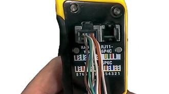
This image illustrates how you can lay out the wires coming from the IC and the components to achieve a more clean-looking build on a breadboard. Note that I removed the Arduino to highlight the breadboard connections.
Lastly, the loop() method checks whether the user pressed one of the two buttons, and then it runs one of the two test-cases according to the button input. Then, it calls a helper method to display the test result using the two LEDs. I used the built-in millis() function to implement a simple debounce delay. You can learn more about that method in another article.
Download the Source Code
You can download the complete source code for this project here. Alternatively, you can simulate the finished project in Tinkercad circuits.
Summary
This article discussed a simple Arduino-based 7400 logic IC tester. The project works because most of the 7400 chips share the same pin layout. Therefore, users can switch out the IC. The Arduino then supplies the chip with known input values, and it then verifies whether the logic IC generates the expected outputs. The Arduino program splits the testing part into several smaller tests that inspect each logic gate in isolation from the other gates in the IC. If all gates return the expected result, the Arduino informs the user that the test was successful.