Matching Inductors to Critical RF Circuit Applications
Przekazane przez: Północnoamerykańscy redaktorzy DigiKey
2025-11-14
Radio frequency (RF) and microwave circuits in applications such as radar, magnetic resonance imaging (MRI), communications systems, and medical electronics require application-specific passive components that are precise, stable, and have low loss. These requirements are especially true for inductors, which must have stable inductance values with minimal variation due to temperature and frequency. They must also preserve signal integrity by minimizing losses and avoiding self-resonant frequencies (SRFs) within the application's bandwidth.
This article reviews the requirements and characteristics of inductors for RF applications. It then introduces high-Q ceramic-core inductors from Knowles that designers can use to address the needs of their most demanding RF applications.
Inductors in RF circuits
Inductors are passive reactive components that oppose changes in current by storing energy in a magnetic field. Comprising a coil of wire, they are relatively simple in construction, but the coiled wire gives rise to several parasitic elements. The equivalent circuit for an inductor includes lead inductance and capacitance, coil resistance, and turn-to-turn capacitance (Figure 1).
 Figure 1: The equivalent circuit of an inductor includes parasitic elements of inductance, capacitance, and resistance. (Image source: Art Pini)
The role of inductors in RF circuits varies from simple chokes to isolate AC from DC signal components to finely tuned devices in tank circuits and filters. They operate at RF and microwave frequencies, where minimizing reflections and standing waves requires component designs with small parasitic capacitance and inductance. In such applications, frequency-dependent effects, such as skin effect and radiation, must also be considered. RF inductors handle small signals where losses cannot be tolerated, requiring a high quality factor (Q) and low equivalent series resistance (ESR). As a result, inductor specifications include not just inductance, tolerance, and power ratings, but also several RF-specific requirements, primarily Q, SRF, and ESR.
What is Q for inductors?
Q is a figure of merit indicating how closely a given inductor comes to being ideal. An ideal inductor would have an impedance consisting exclusively of inductive reactance. Current through the inductor would be ninety degrees out of phase with the applied voltage. A real inductor has parasitic elements, including leakage inductance, capacitance, and resistance (see Figure 1, again). The resistance is due to the series resistance of the wire conductor, the skin effect, core losses, and radiation losses. The DC resistance (DCR) is the primary source of resistance.
Q is a dimensionless figure of merit equal to the ratio of an inductor's inductive reactance to its resistance, per the equation Q = XL/R = (2pfL)/R
Where:
Q is the quality factor
XL is the inductive reactance in ohms (Ω)
f is the frequency in hertz (Hz)
L is the inductance in henries (H)
R is the ESR (Ω)
Q can be thought of as a measure of energy loss in the inductor relative to the stored energy. The higher the Q, the lower the energy loss and the more ideal the inductor’s performance. Q is frequency dependent due to the inductive reactance and resistive skin effects (Figure 2).
 Figure 2: Plots of inductor Q as a function of frequency show its frequency dependence. (Image source: Knowles)
For low losses, Q should be maximized and series resistance minimized.
What is an RF inductor’s SRF?
An RF inductor’s SRF is the frequency at which the inductance, coupled with the parallel parasitic capacitances, forms a parallel resonant circuit. At the SRF, the impedance of the inductor becomes very high, behaving like an open circuit. The inductor looks inductive only up to the SRF (Figure 3).
 Figure 3: A plot shows that inductance as a function of frequency is flat up to the SRF. (Image source: Knowles)
The SRF of an inductor is inversely proportional to its inductance. Higher inductances require an increased number of turns, and the parasitic winding capacitance increases proportionally, resulting in a lower SRF.
Defining inductor ESR
The ESR of an inductor comprises two parts: DCR and frequency-dependent resistance. The frequency-dependent resistance is due to the skin effect, where at high frequencies, the current through a conductor is not uniformly distributed across the entire cross-section of the conductor but tends to concentrate toward the outer surface. The DCR component is relatively easy to measure and is typically listed in the inductor's specifications. The skin effect is frequency-dependent and is generally described as part of the Q plot shown in Figure 2.
High-Q ceramic core inductors for critical RF circuits
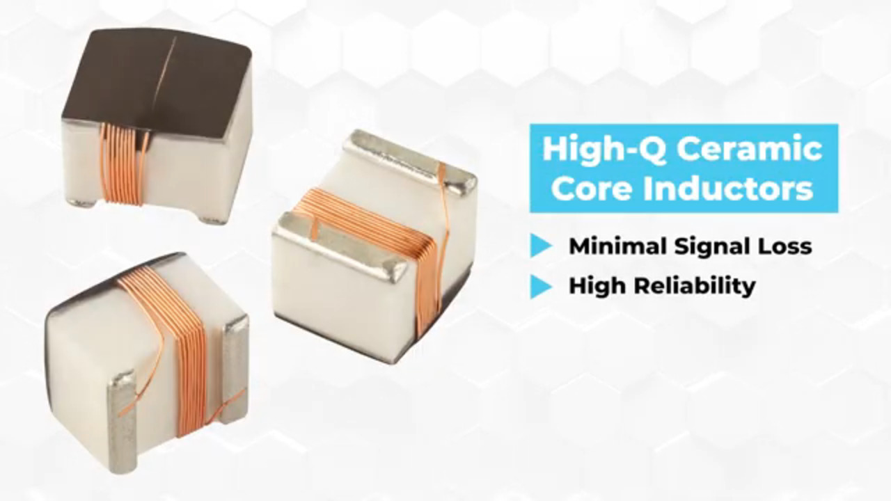
To meet the requirements of critical RF circuits for radar, MRI, communications systems, and medical electronics, Knowles developed the CL1008 series of surface-mount high-Q ceramic wirewound inductors. These highly reliable inductors are designed to operate over a broad frequency range, providing high signal integrity through a combination of high Q and reduced signal losses.
These inductors consist of a non-magnetic ceramic core that serves as a base for the copper wire coil (Figure 4, top). They are also very compact, measuring 0.115" × 0.110" × 0.08" (2.80 mm × 2.60 mm × 2.30 mm) (Figure 4, bottom).
 Figure 4: The CL1008 series of high-Q RF inductors uses a non-magnetic ceramic core (top) and measures 0.115" × 0.110" × 0.08" (bottom). (Image source: Knowles)
The ceramic core provides support for the winding without incurring power losses. This allows for a device structure compatible with surface-mount processes that would be difficult for an air-core inductor.
The coil is attached to the bottom terminations of sintered silver with a copper barrier that is tin-plated. The top side of the inductor features a smooth surface, making it compatible with pick-and-place operations.
As with any such inductor, the inductance is proportional to the number of turns in the coil. This series of inductors is available with inductances ranging from 12 nH to 10 mH, and current ratings from 140 mA to 1000 mA at +85°C and from 70 mA to 1000 mA at +125°C. Their operating temperature range is -55°C to +125°C, and they are RoHS-compliant and halogen-free.
While several manufacturing technologies are available for creating ceramic inductors, including wire-wound, film, and multilayer implementations, the wire-wound ceramic core inductor has some advantages. First, the inductor winding is not confined to a closed package. This allows for more wire turns, resulting in a greater range of achievable inductance values. In addition, the conductor cross-section is not restricted by the printing process used in film and multilayer materials; therefore, heavier wires can be used, which increases the current rating and reduces the resistance. The reduced resistance yields a higher Q.
Ceramic core inductor RF applications
A typical use of RF inductors is in oscillators, such as a Colpitts oscillator shown in Figure 5.
 Figure 5: This Colpitts oscillator uses two RF inductors, one as a tuning component (L1) and the other as a choke (L2). (Image source: Art Pini)
All oscillators use positive feedback to achieve oscillation. In this Colpitts oscillator example, the feedback from the collector to the base of Q1 is via C3 from a tuned tank circuit formed by C1, C2, and L1. They form a pi network that resonates at the frequency determined by L1 and the series combination of C1 and C2. L1 should have a high Q to minimize loss and tighten frequency stability.
Inductor L2 is an RF choke. It allows DC to pass, but prevents the output signal from passing into the power source. L2 needs to have a low DCR to limit voltage losses and a current rating sufficient to power the oscillator. The SRF of an inductor used as a choke should be much higher than the output signal frequency to ensure it behaves inductively across the band of interest.
Inductance-capacitance (LC) filters are another common RF application for inductors. Filters are typically used in series between RF stages to shape the passband of the transmitted signal and limit out-of-band (OOB) energy, including harmonics and electromagnetic interference (EMI). At RF frequencies, filters can be easily implemented using LC designs because the inductance and capacitance required are relatively small, allowing for compact form factors. Filters are classified by their frequency-limiting characteristics as low-pass, high-pass, bandpass (Figure 6), or band-stop.
 Figure 6: A fifth-order Butterworth LC bandpass filter uses five inductors (L1 to L5). (Image source: Art Pini)
This filter features a fifth-order Butterworth configuration, so it uses five LC sections to implement the bandpass frequency response. The factors affecting the selection of inductors include the component's inductance and tolerance, SRF, Q, and DCR.
The SRF of the inductors used must be at least ten times higher than the filter's frequency band to ensure that the inductor behaves predictably. The Q should be as high as possible to ensure filter accuracy. A low DCR is desired to minimize power loss and internal heating.
The inductance value and tolerance of the inductor impact the frequency response of the filter, including the corner frequency locations, and are selected during the filter design process.
Examples of high-Q ceramic core inductors
Knowles’ CL1008 series high-Q ceramic core inductors are designed to optimize signal integrity and efficiency over the broad range of RF and microwave frequencies. For example, the CL1008-2124JQL1T-1 is a 120 nH ±5% ceramic core inductor with a Q of 60 at 350 megahertz (MHz) and an SRF of 900 MHz. Its DCR is 0.63 Ω, and it is rated for 300 mA at 125°C and 600 mA at 85°C.
Lower inductances, compatible with higher frequencies, include the CL1008-2123JQL1T-1, a 12 nH ±5% inductor with a Q of 50 MHz at 500 MHz and an SRF of 3,300 MHz. The lower inductance requires fewer turns and has reduced resistance, specifically 0.09 Ω in this case, resulting in a maximum current rating of 1m000 mA at +125°C.
Examining the CL1008-2823JQL1T-1 and comparing its specifications with those of the other inductors, it is evident that there is a clear relationship between inductance, SRF, Q, and DCR. The CL1008-2823JQL1T-1 is an 82 nH ±5% inductor with a Q of 60 at 350 MHz and an SRF of 1200 MHz. Its DCR is 0.22 Ω, with a maximum current of 370 mA at 125°C and 730 mA at 85°C.
Finally, the CL1008-2474JQL1T-1 is a 470 nH ±5% ceramic core inductor with a Q of 45 at 100 MHz and an SRF of 450 MHz. Its DCR is 1.17 Ω, and its maximum current ratings are 240 mA at 125°C and 470 mA at 85°C.
It is easier to compare the relationship of Q values between different inductances by referring back to Figure 2. Note that the peak Q decreases with increasing inductance.
Conclusion
The Knowles high-Q ceramic core inductors provide RF circuit designers with stable inductance values, high Q, and low ESR for critical RF applications that require excellent signal integrity, minimal power losses, and superior reliability.
Disclaimer: The opinions, beliefs, and viewpoints expressed by the various authors and/or forum participants on this website do not necessarily reflect the opinions, beliefs, and viewpoints of DigiKey or official policies of DigiKey.