Power Distribution Boards: Smart Alternative to Relays
2026-03-30 | By Antonio Velasco
Every vehicle relies on a robust electrical system to operate its basic functions. Whether it’s for engine timing for combustion vehicles or for the power system of an electric vehicle, these electrical systems are essential for performance and reliability. In the automotive industry, these electrical demands only become more intense and stringent. In most cars, there are typically high-current lines that require consistent and stable power, such as pumps and fuel injectors. These subsystems are sensitive and can be damaged easily, making them require protection from electrical abnormalities.
Traditionally, relays and fuses have been used to keep these electrical components safe, but they often need to be replaced because they’re inherently mechanical devices that wear over time and are bulky. What’s more is that they’re relatively slow to draw and won’t always protect the electrical systems in time.
Something I’ve been looking into for automotive applications is a Power Distribution Board (PDB) that replaces these bulky, mechanical fuses and relays with a MOSFET-based solid-state switching that utilizes onboard measurement hardware. This would allow for real-time reporting of the current/voltage and the constant tracking of faults, performing the duties of a switch/fuse while being reusable, fast, and with a higher reliability (hopefully). This blog will talk about the core concepts and the theory behind the circuit schematic and how it was approached.
Why Move Away from Mechanical Relays?
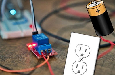
As mentioned, although they’ve been used for many many decades, relays are limited in their performance and behavior. The way that a relay works is through using a small current to control a larger one, essentially like a switch to control a larger current. Think of it like opening and closing a dam; it’s much easier to flick a switch to do so rather than to try to harness the river. The way the small current does this is through creating a magnetic field via a coil to physically move contacts that close and open a circuit.
Here is a typical diagram of a 4-pin relay, where 85 and 86 generate the small magnetic field via the coil to control the high-current switch between 30 and 87.

This method has been used for decades and has been the industry standard. However, because these contacts are physical, they degrade over time and are very bulky. It also performs relatively slowly, as the magnetic field needs to be generated and the switch needs to physically move. As such, this approach is practically outdated and needs to be replaced as technologies improve.
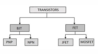
MOSFETs and More
If you’re familiar with MOSFETs, you might’ve noticed that the analogy for a relay is similar to that of a MOSFET. For those who aren’t, MOSFETs are essentially electronic switches that control the flow of electrical current.
In a MOSFET, there is a gate, drain, and source.

When a voltage is applied to the gate (G), current is allowed to flow between the drain and source terminals. Otherwise, without the voltage, the path prevents the flow of current. Notably, the current between the source and drain can be relatively high.
MOSFETs solve all of the issues that traditional relays have:
- There are no moving parts, making their reliability greater and their lifetime longer
- Electricity moves extremely fast, making it easy to mitigate faults and issues
- MOSFETs are very small and compact, making a PCB package for them easy to integrate anywhere
Automotive-grade MOSFETs sit at roughly 10-60A switching per channel and have excellent behavior, and as such are perfect for our applications.
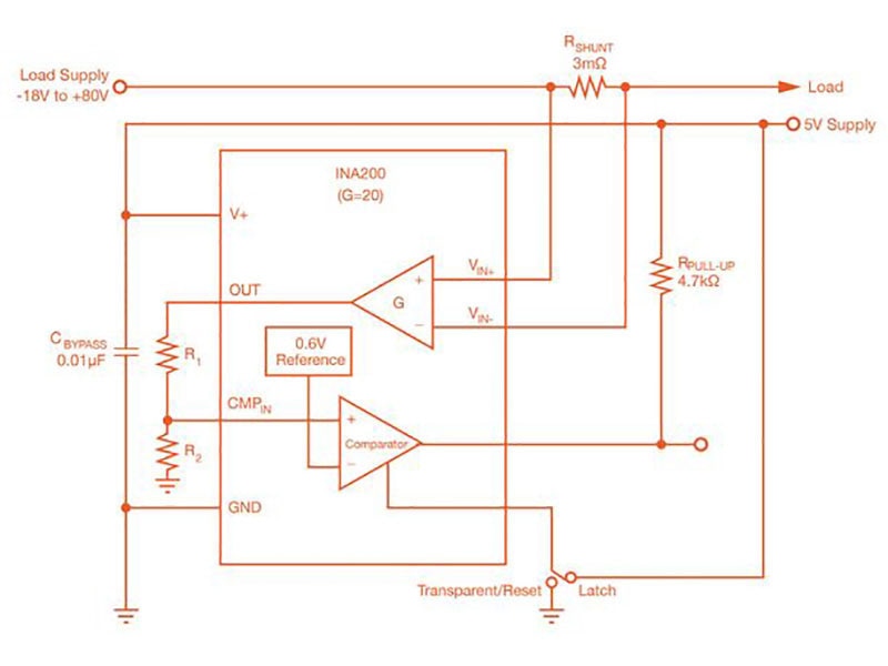
Architecture Overview + Next Steps
The way that the MOSFET will operate is that it will operate as a high-side switch, meaning that it will sit between the battery and the load. Voltage and current would be monitored by a high-side shunt sensor integrated into the driver IC. Voltage would be monitored by a resistor divided into an ADC port on the MCU (we chose an STM32). The MCU also enables constant monitoring, sampling, and logging.
If the MCU detects a high voltage or a fault, it would then open the circuit that the MOSFET would otherwise close during safe conditions.
Another consideration in the design will be to ensure that there is proper thermal management through wide copper pours or stitching vias, as higher current applications can easily lead to higher temperatures.
Throughout the next couple of weeks, we’ll be designing the circuit schematic, sending a PCB design off to print, and testing it. Stay tuned for more!